




24 Port Fiber Optic Terminal Box
Product Overview
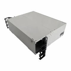
The 24 Port Fiber Terminal Box is a high-performance, space-saving solution designed for fiber optic signal distribution, termination, and protection in FTTH (Fiber to the Home), enterprise networks, and telecom access networks. It integrates termination, splicing, storage, and management functions in one compact unit, ensuring stable signal transmission and easy maintenance.
Features
Industry Standard User Interface, be made of ABS plastic.
Can accommodate 1x4,1x8,1X16, 2x4,2x8 & 2x16 PLC steel tube splitter.
Rainfall resistant, outdoor using, IP66.
Can load 24pcs LC, FC, ST, SC … adapters.
Wall mounting and pole mounting application.
2pcs cable entry ports;
24pcs exit ports for FTTH drop cable.
Specification
|
Capacity |
Dimension |
Remark |
|
Max. 24fibers |
274.3x334.2x114.1mm |
Can load max.2pcs splitter box Can load max.24pcs SC simplex, FC simplex, LC duplex … adapters |
Application
• FTTH (Fiber to the Home) access networks (residential communities, apartment buildings
• Enterprise campus networks (office buildings, data centers, industrial parks)
• Telecom and ISP (Internet Service Provider) access networks
• Security monitoring systems (fiber optic camera signal termination)
• Outdoor communication projects (street cabinets, rural broadband deployment)
Installation Preparation
1 Tools Required
• Fiber optic fusion splicer
• Fiber cleaver
• Cable stripper
• Screwdriver set (Phillips and flat-head)
• Cable cutter
• Optical power meter (for testing)
• Cleaning kit (alcohol wipes, lint-free cloth, fiber cleaning pens)
2 Site Requirements
• For indoor installation: Choose a dry, well-ventilated location with stable temperature and humidity. Ensure sufficient space for cable routing and maintenance (minimum 30cm of clearance around the Box).
• For outdoor installation: Select a location away from water sources, heat sources, and mechanical damage. Use the provided wall brackets or pole-mounting kits for secure installation, ensuring the Box is sealed tightly to prevent water ingress.
• Ensure that the installation surface is flat and firm to support the weight of the Box and connected cables.
3. Installation and Operation Steps
3.1 Unpacking and Inspection
Open the packaging carefully and take out all components.
Inspect the Box for any physical damage (such as cracks, dents, or scratches) during transportation.
3.2 Check if all package contents are complete and free of defects. If any damage or missing parts are found, contact the supplier immediately.
4 Mounting the Box
4.1 Wall-Mounted Installation
Mark the mounting holes on the wall according to the hole positions on the Box's back panel (refer to the dimension drawing in Appendix A).
Drill holes at the marked positions with a drill bit matching the size of the provided screws.
4.2Insert the expansion tubes into the drilled holes (if installing on concrete or brick walls).
Align the Box's mounting holes with the expansion tubes or pre-drilled holes, and fix the Box to the wall using the provided screws. Tighten the screws evenly to ensure the Box is stable and level.
Rack-Mounted Installation (for 19-inch rack models)
Install the rack-mount brackets onto the Box using the provided screws.
Slide the Box into the 19-inch standard rack and align the bracket holes with the rack holes. Secure the Box to the rack with rack screws, ensuring it is firmly fixed and does not shake.
5.Fiber Cable Entry and Fixing
Remove the cable entry gland on the side or bottom of the Box (depending on the model).
Strip the outer sheath of the incoming fiber optic cable (length: 1.5-2m) using a cable stripper, being careful not to damage the inner fibers.
Arrange the stripped fiber optic cable through the cable entry gland and into the Box. Ensure that the cable is not twisted or pulled tightly.
Fix the cable to the cable clamp inside the Box using cable ties to prevent movement. The outer sheath of the cable should be securely clamped to avoid stress on the fibers.
Tighten the cable entry gland to ensure a waterproof and dustproof seal (especially for outdoor models).
6.Fiber Termination and Splicing
Open the Box's cover and take out the splice tray.
Separate the individual fibers from the cable core and strip the buffer coating (length: 3-5cm) using a fiber stripper.
Clean the stripped fibers with an alcohol wipe to remove any oil or dust.
Cleave the fibers with a fiber cleaver at a 90° angle to ensure a flat and smooth end face.
Place the cleaved fibers into the fusion splicer and perform the fusion splicing operation according to the splicer's user manual.
After splicing, inspect the splice joint using the splicer's built-in microscope to ensure good quality (no bubbles, cracks, or misalignment).
Store the spliced fibers in the splice tray's fiber grooves, and fix them with fiber retainers to avoid stress on the splices.
Close the splice tray and place it back into the Box.
7.Fiber Connection to Adapters
Take the pigtails (if used) and strip the buffer coating of the pigtail fibers (length: 3-5cm), then clean and cleave them.
Fusion splice the pigtail fibers with the incoming fibers (following the steps in 4.4) and store the splices in the splice tray.
Insert the connector end of the pigtail into the corresponding adapter on the adapter panel. Ensure a firm connection (you will hear a "click" when properly inserted).
Repeat the above steps for all 24 ports until all fibers are terminated and connected.
Install the dust caps on any unused adapters to prevent dust and contamination.
8. Testing and Verification
Connect an optical power meter to one end of the fiber link and a light source to the other end.
Measure the insertion loss of each port. The loss should be ≤0.3dB (single-mode) or ≤0.5dB (multimode). If the loss exceeds the specified value, check the splice quality and connector connection, and rework if necessary.
Verify the return loss using an optical time-domain reflectometer (OTDR) if available. The return loss should meet the specifications in 1.2.
After confirming that all ports are working normally, close the Box's cover and fasten the screws tightly.
Drawings:(mm)

Thank you for choosing our 24 port fiber terminal box. If you have questions about the 24 port fiber terminal box's installation, compatibility or maintenance, don't hesitate to reach out.


Hot Tags: 24 port fiber optic terminal box, China 24 port fiber optic terminal box manufacturers, suppliers, factory, 96 fiber terminal box, 12 Fibers FTTH Drop Cable Box, 1port fiber terminal box, Fiber Splice Box Outdoor, ftth drop cable box, 24 Port Fiber Optic Terminal Box
You Might Also Like


Send Inquiry